What are PNP and NPN transistors?
PNP and NPN are bipolar junction transistors (BJTs). BJTs are made of doped materials and allow current amplification. It can be configured as PNP and NPN. PNP and NPN transistors provide amplification or switching capability.
What is the difference between PNP and NPN?
It’s easy to remember that NPN stands for Negative-Positive-Negative and PNP stands for Positive-Negative-Positive transistors. Let’s take a closer look at how NPN and PNP transistors work.
NPN transistor is powered on when enough current is supplied from the transistor base to the emitter. Thus, the NPN transistor base has to be connected to a positive voltage and the emitter connected to negative voltage for current to flow into the base. When enough current is flowing from the base into the emitter, the transistor switches on directing current flow from collector to the emitter instead of the transistor base to the emitter. The PNP transistor works in the opposite. In PNP transistor, current normally flows from the transistor's emitter to the base, and when enough current flows from emitter to the base the transistor turns on directing current from emitter to collector.
Briefly, the NPN transistor requires positive current from the base to the emitter and PNP requires negative current to the base, but current must flow out from the base to ground.
![]()
– base terminal; E – emitter terminal; C – collector terminal
Here is a video link below which can explain how NPN and PNP transistors work in more detail:
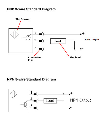
PNP and NPN transistor output signal and load resistor
Various optical, inductive, capacitance, etc. sensors have an output signal named PNP NO, PNP NC, NPN NO, NPN NC all these signals are simply ON/OFF switch, but instead of dry contact, we have output transistor mounted. Transistor has the output polarity (unlike the dry contact). How should we understand these outputs:
PNP - (PNP transistor) NO – normally opened, that means there is no voltage on the output while the sensor is not actuated (see picture, PNP sensor output connector is no. 4). When the sensor is actuated we will have +24 V on connector no. 4. This +24V signal can be connected directly to PLC or for any other proposes such as relay actuating, alarm actuating. Usually, current limitation in proximity sensors is up to 200 mA, that is why in all schemes it is shown that output is connected via a resistor, in reality, this resistor is built in your plc, it could be your relay coil or indication lamp. If we will connect the output directly to the GND (the minus cable) we will have a short circuit, which means current would rise and reach the maximal current of power supply. So if we have for example 5A power supply, short-circuiting will exceed the sensor current limit and it will be damaged.
If we have the NPN NC sensor that means our sensor is equipped with NPN transistor on the output and the sensor is normally closed – that means we have output signal at high state while the sensor is not actuated. Instead of grounding, we are using the positive cable.